Python
 Python 是使用廣泛的程式設計語言,其備受青睞與其語法樣式有很大關係。Python 的可讀性很高,因此較許多其他語言更容易瞭解。Python 支援模組與套件,可嵌入至既有應用程式中。本節中的範例假定您對 Python 有基本瞭解。若要取得有關如何正常使用 Python 的資訊,Python.org 上的「入門」頁面是良好的資源。
視覺程式設計與文字程式設計的對比
為什麼要在 Dynamo 的視覺程式設計環境中使用文字程式設計?我們在第 1.1 章討論過,視覺程式設計有許多優勢。您可藉此在直觀視覺介面中建立程式時,不必學習特殊語法。但是,視覺程式可能會變得雜亂,有時會缺少功能。例如,Python 會提供可實現程度高得多的方法,以編寫條件陳述式 (if/then) 及迴圈。Python 是功能強大的工具,可以延伸 Dynamo 的功能,您可藉此使用幾行簡潔的程式碼來取代許多節點。
視覺程式: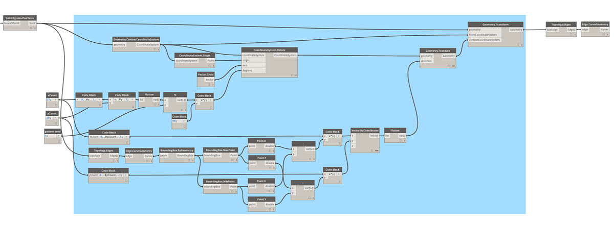
文字程式:
import clr
clr.AddReference('ProtoGeometry')
from Autodesk.DesignScript.Geometry import *

solid = IN[0]
seed = IN[1]
xCount = IN[2]
yCount = IN[3]

solids = []

yDist = solid.BoundingBox.MaxPoint.Y-solid.BoundingBox.MinPoint.Y
xDist = solid.BoundingBox.MaxPoint.X-solid.BoundingBox.MinPoint.X

for i in xRange:
for j in yRange:
fromCoord = solid.ContextCoordinateSystem
toCoord = fromCoord.Rotate(solid.ContextCoordinateSystem.Origin,Vector.ByCoordinates(0,0,1),(90*(i+j%val)))
vec = Vector.ByCoordinates((xDist*i),(yDist*j),0)
toCoord = toCoord.Translate(vec)
solids.append(solid.Transform(fromCoord,toCoord))

OUT = solids
Python 節點
與程式碼塊類似,Python 節點是視覺程式設計環境中的腳本介面。Python 節點位於資源庫中的「Core」>「Scripting」下。按兩下節點將開啟 python 腳本編輯器 (您也可以在節點上按一下右鍵,然後選取「編輯...」)。
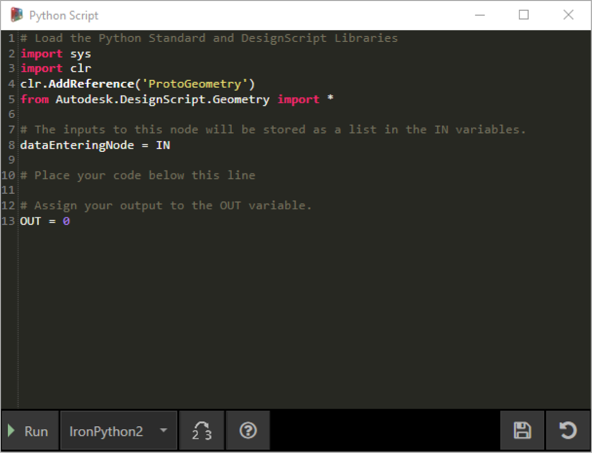
您會注意到頂部有一些重複使用文字,其目的是協助您參考將需要的資源庫。輸入儲存於 IN 陣列中。透過為 OUT 變數指定值,會將這些值傳回至 Dynamo。
藉由 Autodesk.DesignScript.Geometry 資源庫,您可以使用與程式碼塊類似的圓點符號。若要取得有關 Dynamo 語法的更多資訊,請參閱第 7.2 章以及 DesignScript 指南。鍵入幾何圖形類型,例如「Point.」。將顯示建立及查詢點的方法清單。
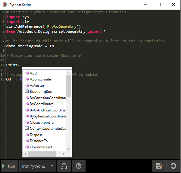
這些方法包括建構函式 (例如 ByCoordinates)、動作 (例如 Add) 以及查詢 (例如 X、Y 與 Z 座標)。
練習
下載此練習隨附的範例檔案 (按一下右鍵,然後按一下「連結另存為...」)。附錄中提供範例檔案的完整清單。Python_Custom-Node.dyn
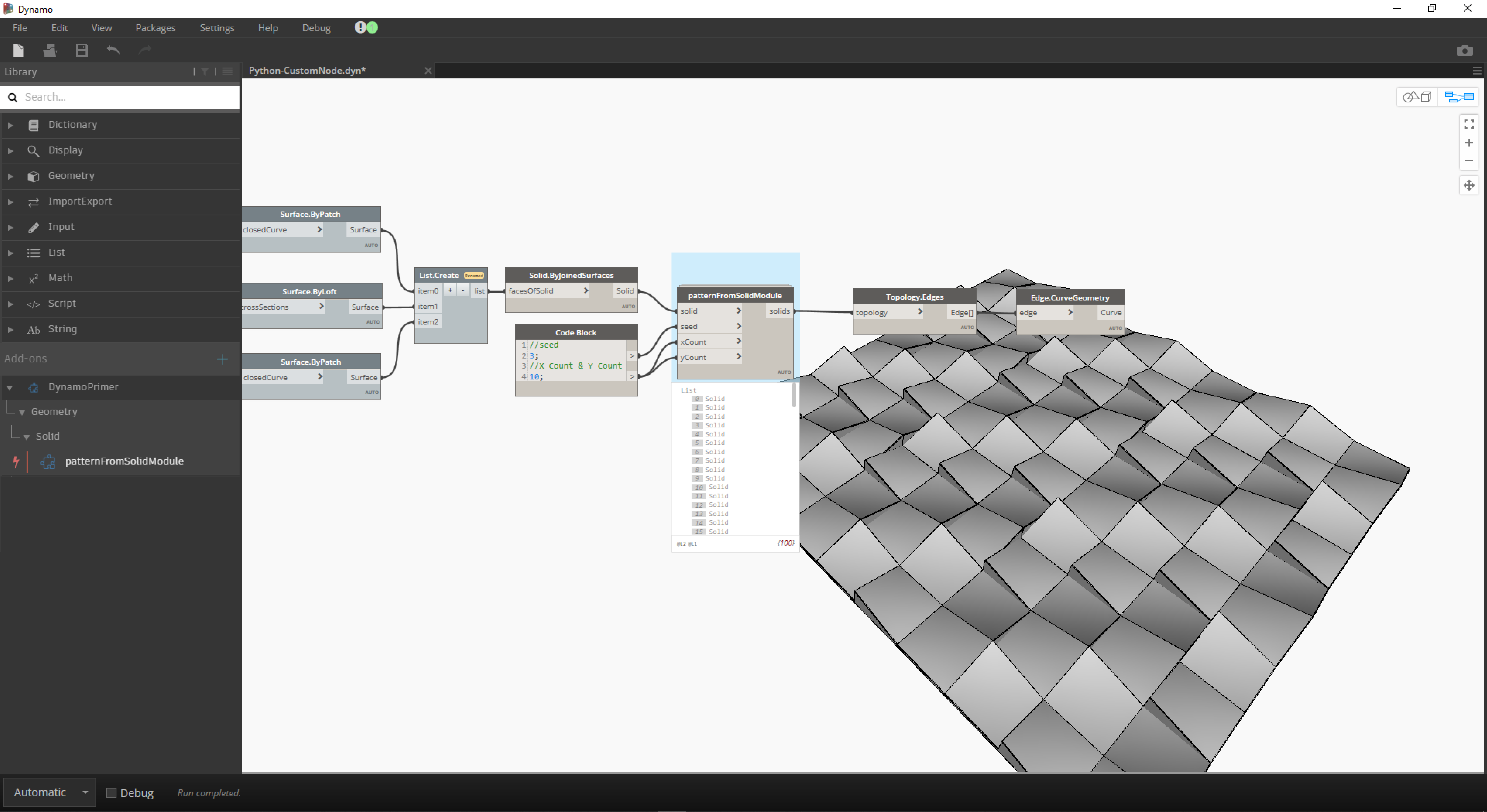
在此範例中,我們將編寫從實體模組建立樣式的 python 腳本,然後將其轉換為自訂節點。首先,使用 Dynamo 節點建立實體模組。
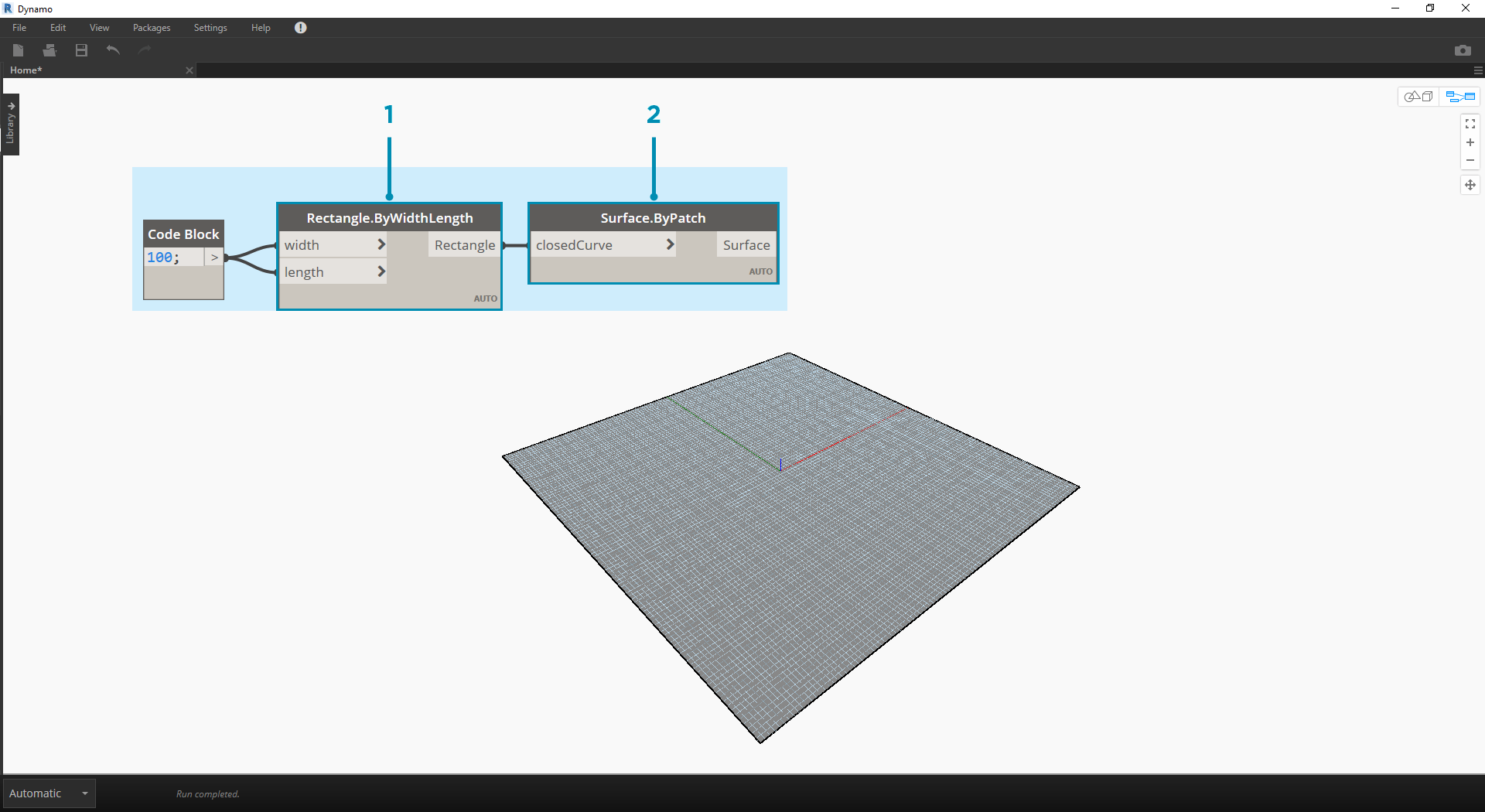
- Rectangle.ByWidthLength:建立將做為實體基準的矩形。
- Surface.ByPatch:將矩形連接至「closedCurve」輸入以建立底部曲面。
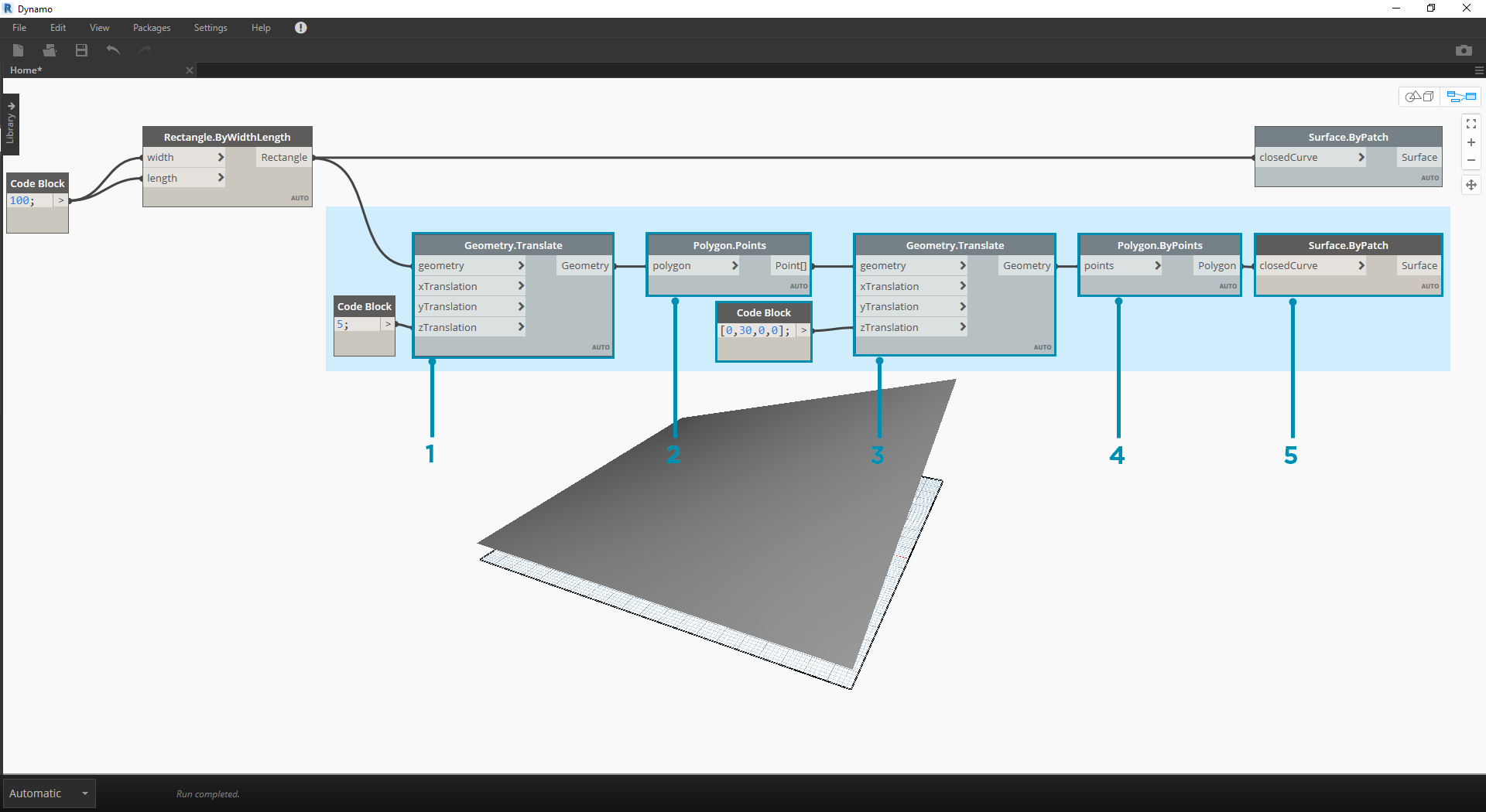
- Geometry.Translate:將矩形連接至「geometry」輸入以將其上移,使用程式碼塊指定實體的基準厚度。
- Polygon.Points:查詢平移的矩形以萃取角點。
- Geometry.Translate:使用程式碼塊建立包含四個值 (對應於四個點) 的清單,同時將實體的一個角點上移。
- Polygon.ByPoints:使用平移的點重新建構頂部多邊形。
- Surface.ByPatch:連接多邊形以建立頂部曲面。
現在我們已建立頂部與底部曲面,接下來在兩個縱斷面之間進行斷面混成,以建立實體的側面。
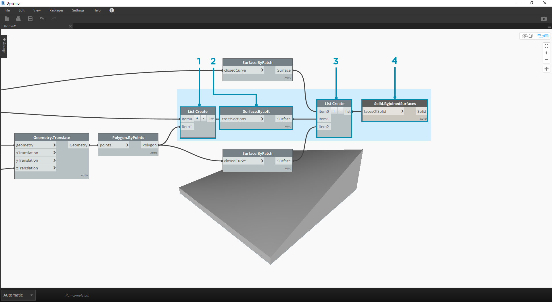
- List.Create:將底部矩形與頂部多邊形連接至索引輸入。
- Surface.ByLoft:對兩個縱斷面進行斷面混成,以建立實體的側面。
- List.Create:將頂部、側面與底部的曲面連接至索引輸入,以建立曲面清單。
- Solid.ByJoinedSurfaces:接合曲面以建立實體模組。
現在我們已建立實體,接下來將 Python Script節點放至工作區。
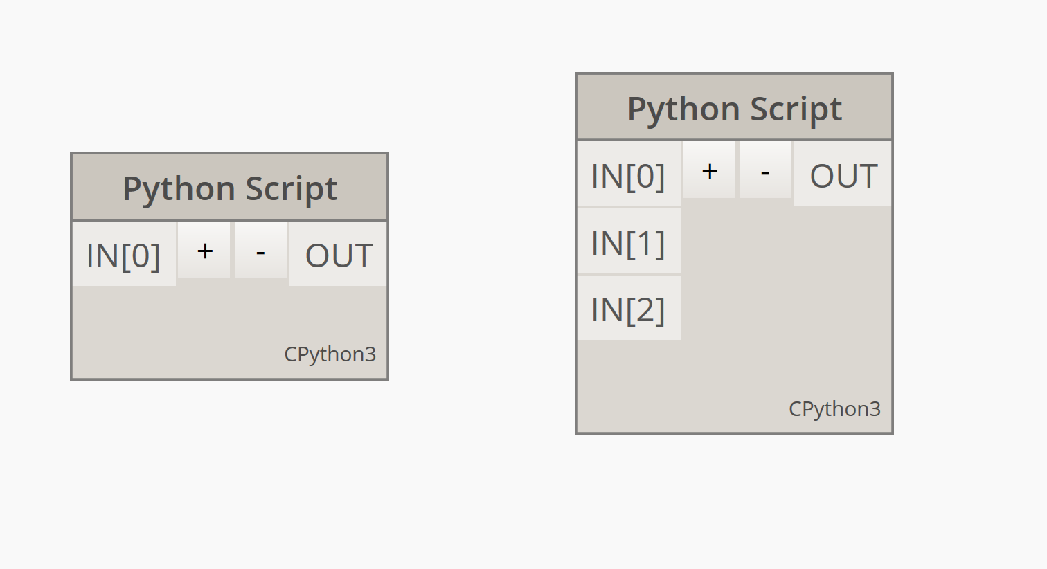
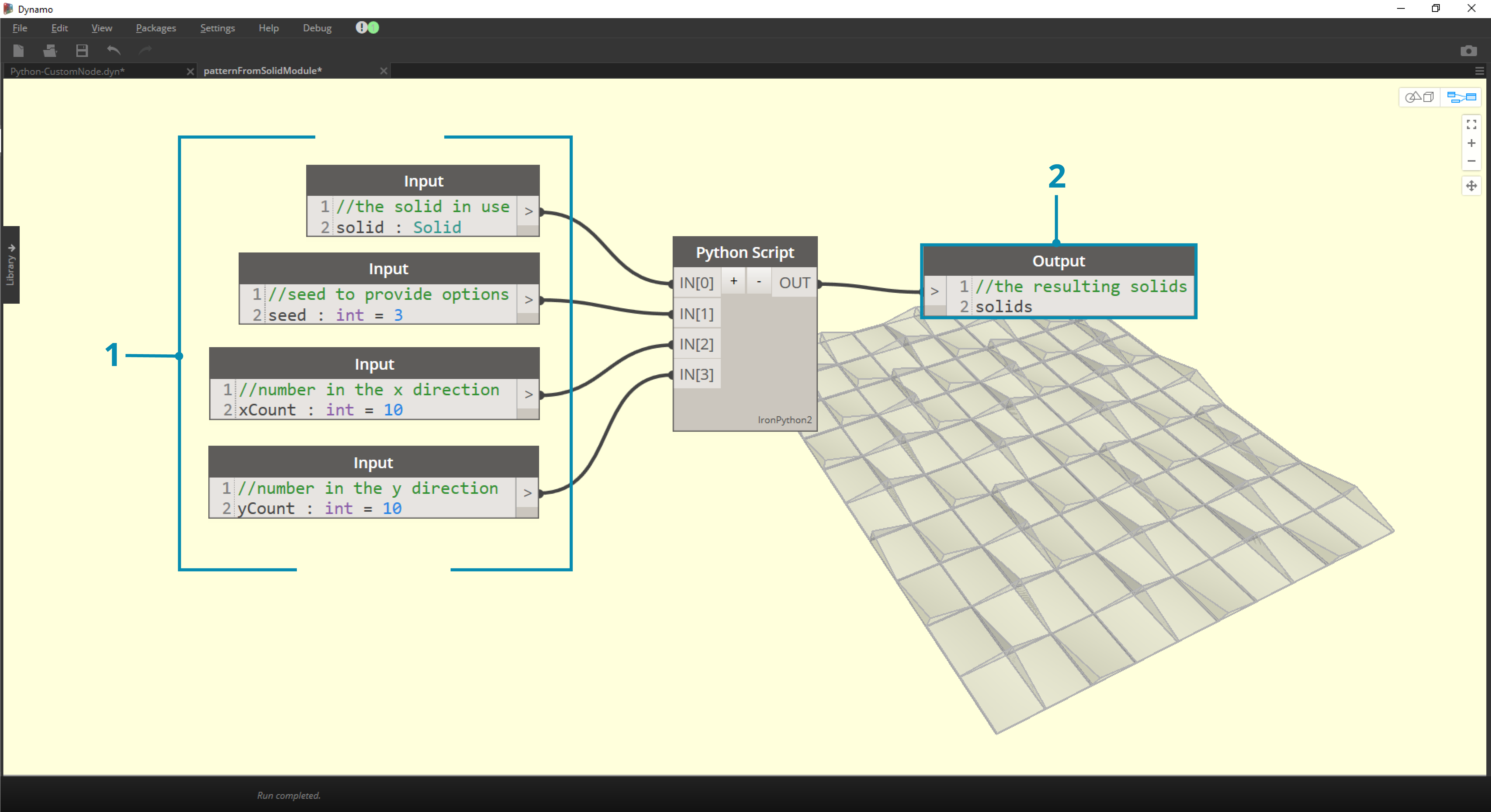
若要加入其他輸入至節點,請關閉編輯器,然後按一下節點上的「+」圖示。輸入命名為 IN[0]、IN[1] 等以指示其代表清單中的項目。
我們從定義輸入與輸出開始。按兩下節點以開啟 python 編輯器。
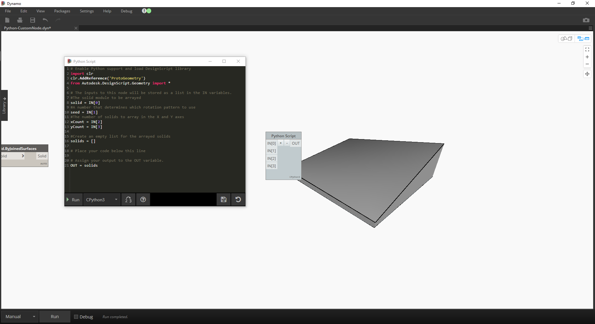
# Enable Python support and load DesignScript library
import clr
clr.AddReference('ProtoGeometry')
from Autodesk.DesignScript.Geometry import *

# The inputs to this node will be stored as a list in the IN variables.
#The solid module to be arrayed
solid = IN[0]
#A number that determines which rotation pattern to use
seed = IN[1]
#The number of solids to array in the X and Y axes
xCount = IN[2]
yCount = IN[3]

#Create an empty list for the arrayed solids
solids = []

# Place your code below this line

# Assign your output to the OUT variable.
OUT = solids
在我們進行練習時,此程式碼會更容易理解。接下來,我們需要考慮需要哪些資訊以排列實體模組。首先,我們需要知道實體的標註,以確定平移距離。由於存在邊界框錯誤,我們不得不使用邊曲線幾何圖形來建立邊界框。
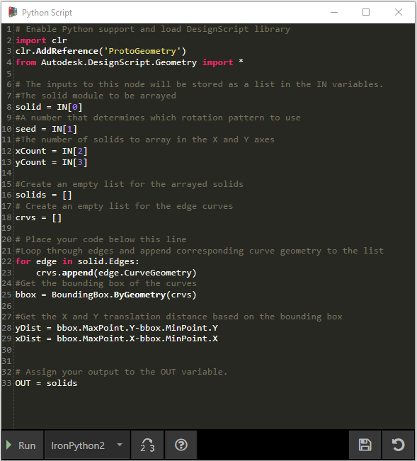
看一下 Dynamo 中的 Python 節點。請注意,我們使用的語法與 Dynamo 節點標題中的語法相同。註釋的程式碼如下。
# Enable Python support and load DesignScript library
import clr
clr.AddReference('ProtoGeometry')
from Autodesk.DesignScript.Geometry import *

# The inputs to this node will be stored as a list in the IN variables.
#The solid module to be arrayed
solid = IN[0]
#A number that determines which rotation pattern to use
seed = IN[1]
#The number of solids to array in the X and Y axes
xCount = IN[2]
yCount = IN[3]

#Create an empty list for the arrayed solids
solids = []
# Create an empty list for the edge curves
crvs = []

# Place your code below this line
#Loop through edges and append corresponding curve geometry to the list
for edge in solid.Edges:
crvs.append(edge.CurveGeometry)
#Get the bounding box of the curves
bbox = BoundingBox.ByGeometry(crvs)

#Get the X and Y translation distance based on the bounding box
yDist = bbox.MaxPoint.Y-bbox.MinPoint.Y
xDist = bbox.MaxPoint.X-bbox.MinPoint.X

# Assign your output to the OUT variable.
OUT = solids
由於我們將平移並旋轉實體模組,因此接下來使用 Geometry.Transform 作業。看一下 Geometry.Transform 節點,我們知道需要來源座標系統與目標座標系統,以平移實體。來源是實體的關聯座標系統,而目標是所排列每個模組的不同座標系統。這意味著我們必須循環使用 x 值與 y 值,以便每次以不同方式平移座標系統。
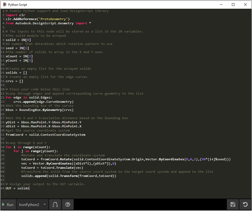
看一下 Dynamo 中的 Python 節點。註釋的程式碼如下。
# Enable Python support and load DesignScript library
import clr
clr.AddReference('ProtoGeometry')
from Autodesk.DesignScript.Geometry import *

# The inputs to this node will be stored as a list in the IN variables.
#The solid module to be arrayed
solid = IN[0]
#A number that determines which rotation pattern to use
seed = IN[1]
#The number of solids to array in the X and Y axes
xCount = IN[2]
yCount = IN[3]

#Create an empty list for the arrayed solids
solids = []
# Create an empty list for the edge curves
crvs = []

# Place your code below this line
#Loop through edges and append corresponding curve geometry to the list
for edge in solid.Edges:
crvs.append(edge.CurveGeometry)
#Get the bounding box of the curves
bbox = BoundingBox.ByGeometry(crvs)

#Get the X and Y translation distance based on the bounding box
yDist = bbox.MaxPoint.Y-bbox.MinPoint.Y
xDist = bbox.MaxPoint.X-bbox.MinPoint.X
#get the source coordinate system
fromCoord = solid.ContextCoordinateSystem

#Loop through X and Y
for i in range(xCount):
for j in range(yCount):
#Rotate and translate the coordinate system
toCoord = fromCoord.Rotate(solid.ContextCoordinateSystem.Origin,Vector.ByCoordinates(0,0,1),(90*(i+j%seed)))
vec = Vector.ByCoordinates((xDist*i),(yDist*j),0)
toCoord = toCoord.Translate(vec)
#Transform the solid from the source coord system to the target coord system and append to the list
solids.append(solid.Transform(fromCoord,toCoord))

# Assign your output to the OUT variable.
OUT = solids
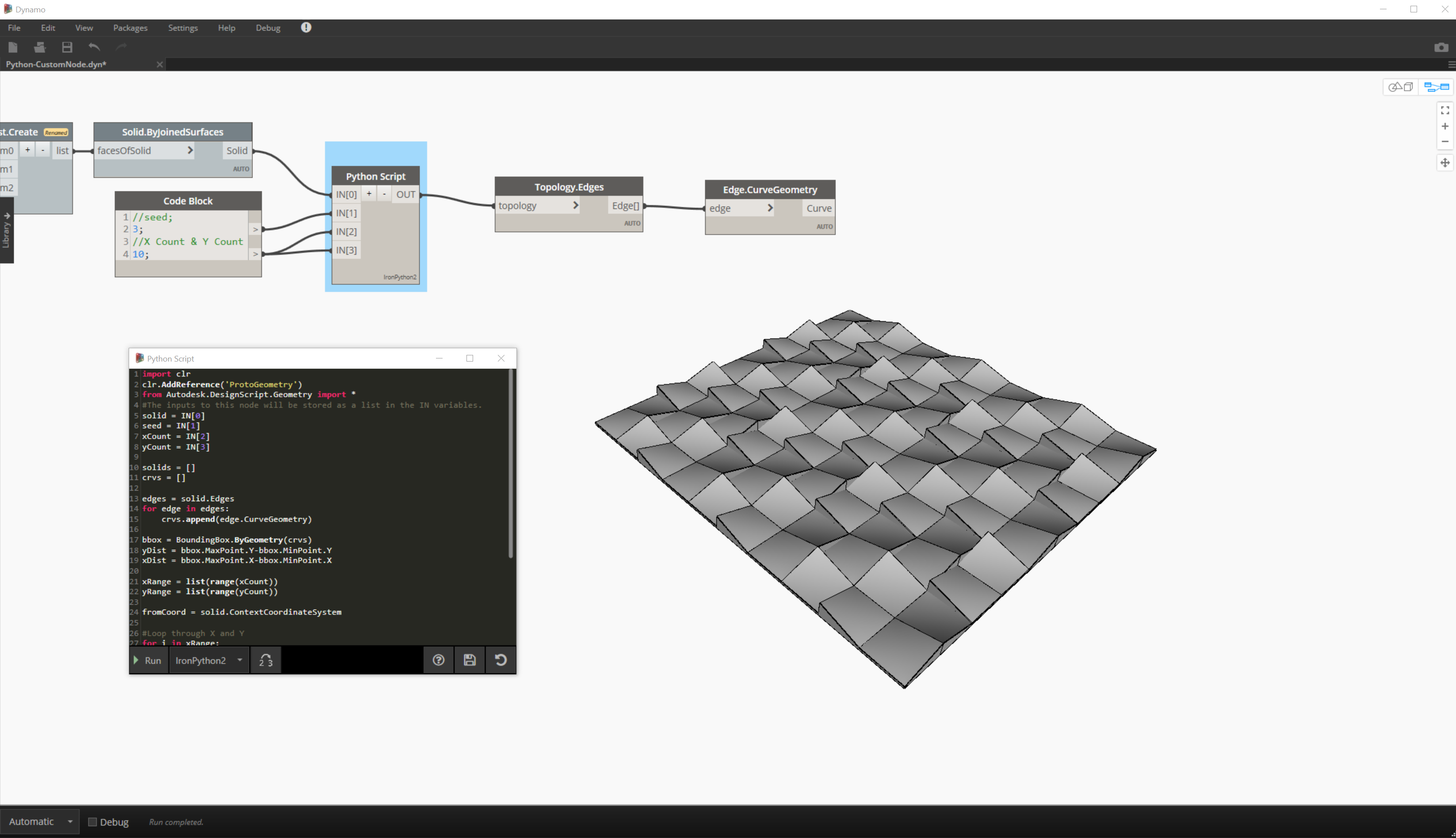
在 Python 節點上按一下「執行」,可以執行程式碼。

請嘗試變更種子值以建立不同的樣式。您也可以變更實體模組本身的參數,以取得不同的效果。在 Dynamo 2.0 中,您可以直接變更種子並按一下「執行」,不用關閉 Python 視窗。
現在我們已建立有用的 python 腳本,接下來將其另存成自訂節點。選取 Python Script 節點,按一下右鍵,然後選取「從選項新增節點」。
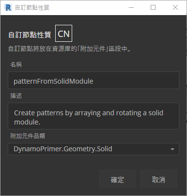
指定名稱、描述與品類。
這將開啟新工作區,從中將編輯自訂節點。
- Input:變更輸入名稱以更具描述性,然後加入資料類型及預設值。
- Output:變更輸出名稱,將節點另存成 .dyf 檔案。
自訂節點將反映我們剛剛進行的變更。