Python
 Python 是一种广泛使用的编程语言,其流行程度与其语法风格有很大关系。它的可读性很高,因此比许多其他语言更易于学习。Python 支持模块和软件包,并且可以嵌入到现有应用程序中。本部分中的示例假定您对 Python 基本熟悉。有关如何启动和运行 Python 的信息,请访问 Python.org 上的“快速入门”页面(这是一个很好的资源)。
可视化与文本编程
为什么要在 Dynamo 的可视化编程环境中使用文本编程?正如我们在第 1.1 章中所述,可视化编程具有许多优势。它使您无需在直观的可视化界面中学习特殊语法即可创建程序。但是,可视化程序可能会变得混乱,有时可能会在功能上有所降低。例如,Python 提供了更多可实现的方法来编写条件语句 (if/then) 和循环。Python 是一款功能强大的工具,可扩展 Dynamo 的功能,并允许您将许多节点替换为几行简明的代码。
可视化程序:
文本程序:
import clr
clr.AddReference('ProtoGeometry')
from Autodesk.DesignScript.Geometry import *

solid = IN[0]
seed = IN[1]
xCount = IN[2]
yCount = IN[3]

solids = []

yDist = solid.BoundingBox.MaxPoint.Y-solid.BoundingBox.MinPoint.Y
xDist = solid.BoundingBox.MaxPoint.X-solid.BoundingBox.MinPoint.X

for i in xRange:
for j in yRange:
fromCoord = solid.ContextCoordinateSystem
toCoord = fromCoord.Rotate(solid.ContextCoordinateSystem.Origin,Vector.ByCoordinates(0,0,1),(90*(i+j%val)))
vec = Vector.ByCoordinates((xDist*i),(yDist*j),0)
toCoord = toCoord.Translate(vec)
solids.append(solid.Transform(fromCoord,toCoord))

OUT = solids
Python 节点
与代码块一样,Python 节点也是可视化编程环境中的脚本编写界面。Python 节点位于库中的“核心”>“脚本编写”下。双击节点会打开 Python 脚本编辑器(也可以在节点上单击鼠标右键,然后选择“编辑...”)。
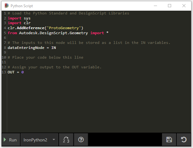
您会注意到顶部的一些样本文字,旨在帮助您引用所需的库。输入存储在 IN 数组中。通过将值指定给 OUT 变量,可以将这些值返回到 Dynamo。
Autodesk.DesignScript.Geometry 库允许您使用与代码块类似的点符号。有关 Dynamo 语法的详细信息,请参见第 7.2 章以及《DesignScript 手册》。键入几何图形类型(例如“Point.”)将显示用于创建和查询点的一列方法。

方法包括构造函数(如 ByCoordinates)、操作(如 Add)和查询(如 X、Y 和 Z 坐标)。
练习
下载本练习随附的示例文件(单击鼠标右键,然后单击“将链接另存为...”)。可以在附录中找到示例文件的完整列表。Python_Custom-Node.dyn
在本示例中,我们将编写一个 Python 脚本,该脚本用于从实体模块创建图案,并将其转换为自定义节点。 首先,我们使用 Dynamo 节点创建实体模块。

- Rectangle.ByWidthLength:创建一个矩形,它将作为实体的基础。
- Surface.ByPatch:将矩形连接到“closedCurve”输入以创建底部曲面。

- Geometry.Translate:将矩形连接到“geometry”输入以向上移动它,从而使用代码块指定实体的基础厚度。
- Polygon.Points:查询平移的矩形以提取角点。
- Geometry.Translate:使用代码块创建与四个点对应的一列四个值,从而向上平移实体的一个角。
- Polygon.ByPoints:使用平移的点来重建顶部多边形。
- Surface.ByPatch:连接多边形以创建顶部曲面。
现在我们有了顶面和底面,接下来让我们在两个轮廓之间放样来创建实体的侧面。

- List.Create:将底部矩形和顶部多边形连接到索引输入。
- Surface.ByLoft:放样两个轮廓以创建实体的侧面。
- List.Create:将顶面、侧面和底面连接到索引输入以创建曲面列表。
- Solid.ByJoinedSurfaces:连接曲面以创建实体模块。
现在我们有了实体,接下来将 Python 脚本节点拖动到工作空间。

要向节点添加其他输入,请关闭编辑器,然后单击节点上的“+”图标。输入命名为 IN[0]、IN[1] 等,以指示它们表示列表中的各项目。
首先定义输入和输出。双击该节点以打开 Python 编辑器。

# Enable Python support and load DesignScript library
import clr
clr.AddReference('ProtoGeometry')
from Autodesk.DesignScript.Geometry import *

# The inputs to this node will be stored as a list in the IN variables.
#The solid module to be arrayed
solid = IN[0]
#A number that determines which rotation pattern to use
seed = IN[1]
#The number of solids to array in the X and Y axes
xCount = IN[2]
yCount = IN[3]

#Create an empty list for the arrayed solids
solids = []

# Place your code below this line

# Assign your output to the OUT variable.
OUT = solids
随着我们在练习中的进展,此代码将更有意义。接下来,我们需要考虑排列实体模块所需的信息。首先,我们需要知道实体的尺寸以确定平动距离。由于存在边界框 Bug,因此我们需要使用边曲线几何图形来创建边界框。

在 Dynamo 中查看 Python 节点。请注意,我们使用的语法与在 Dynamo 中节点标题中看到的语法相同。注释的代码如下。
# Enable Python support and load DesignScript library
import clr
clr.AddReference('ProtoGeometry')
from Autodesk.DesignScript.Geometry import *

# The inputs to this node will be stored as a list in the IN variables.
#The solid module to be arrayed
solid = IN[0]
#A number that determines which rotation pattern to use
seed = IN[1]
#The number of solids to array in the X and Y axes
xCount = IN[2]
yCount = IN[3]

#Create an empty list for the arrayed solids
solids = []
# Create an empty list for the edge curves
crvs = []

# Place your code below this line
#Loop through edges and append corresponding curve geometry to the list
for edge in solid.Edges:
crvs.append(edge.CurveGeometry)
#Get the bounding box of the curves
bbox = BoundingBox.ByGeometry(crvs)

#Get the X and Y translation distance based on the bounding box
yDist = bbox.MaxPoint.Y-bbox.MinPoint.Y
xDist = bbox.MaxPoint.X-bbox.MinPoint.X

# Assign your output to the OUT variable.
OUT = solids
由于我们将平移并旋转实体模块,因此我们使用 Geometry.Transform 操作。通过查看 Geometry.Transform 节点,我们知道需要源坐标系和目标坐标系来变换实体。源是实体的上下文坐标系,而目标是每个阵列模块的不同坐标系。这意味着我们需要遍历 X 和 Y 值,以每次变换不同的坐标系。

在 Dynamo 中查看 Python 节点。注释的代码如下。
# Enable Python support and load DesignScript library
import clr
clr.AddReference('ProtoGeometry')
from Autodesk.DesignScript.Geometry import *

# The inputs to this node will be stored as a list in the IN variables.
#The solid module to be arrayed
solid = IN[0]
#A number that determines which rotation pattern to use
seed = IN[1]
#The number of solids to array in the X and Y axes
xCount = IN[2]
yCount = IN[3]

#Create an empty list for the arrayed solids
solids = []
# Create an empty list for the edge curves
crvs = []

# Place your code below this line
#Loop through edges and append corresponding curve geometry to the list
for edge in solid.Edges:
crvs.append(edge.CurveGeometry)
#Get the bounding box of the curves
bbox = BoundingBox.ByGeometry(crvs)

#Get the X and Y translation distance based on the bounding box
yDist = bbox.MaxPoint.Y-bbox.MinPoint.Y
xDist = bbox.MaxPoint.X-bbox.MinPoint.X
#get the source coordinate system
fromCoord = solid.ContextCoordinateSystem

#Loop through X and Y
for i in range(xCount):
for j in range(yCount):
#Rotate and translate the coordinate system
toCoord = fromCoord.Rotate(solid.ContextCoordinateSystem.Origin,Vector.ByCoordinates(0,0,1),(90*(i+j%seed)))
vec = Vector.ByCoordinates((xDist*i),(yDist*j),0)
toCoord = toCoord.Translate(vec)
#Transform the solid from the source coord system to the target coord system and append to the list
solids.append(solid.Transform(fromCoord,toCoord))

# Assign your output to the OUT variable.
OUT = solids

单击 Python 节点上的“运行”将允许代码执行。

尝试更改种子值以创建不同的图案。还可以更改实体模块本身的参数以实现不同的效果。在 Dynamo 2.0 中,只需更改种子并单击“运行”即可,而无需关闭 Python 窗口。
现在,我们已创建了一个有用的 Python 脚本,接下来我们将它另存为一个自定义节点。选择 Python 脚本节点,单击鼠标右键,然后选择“从当前选择新建节点”。

指定名称、描述和类别。
这将打开一个新的工作空间,可以在其中编辑自定义节点。

- 输入:将输入名称更改为更具描述性的名称,并添加数据类型和默认值。
- 输出:更改输出名称,将节点另存为 .dyf 文件。

自定义节点反映了我们刚才所做的更改。